When it comes to helping in the weight distribution of the vehicle, and removing weight from
over the front axel, one popular modification is the relocation of the battery. This is just
a quick informational about my battery relocation, unfortunately not much of a DIY since most
of the work is fishing wires through small areas.
Required Tools
There are a few tools required to be able to do this job successfully.
45ft-50ft 2AWG Welding Cable (www.cableyard.com)
200A Tsunami Circuit Breaker
Tsnuami Positive and Negative Battery Terminals
Scorpion Distribution Block
Scorpion Screw Set Ring Terminals
Trunk Relocation
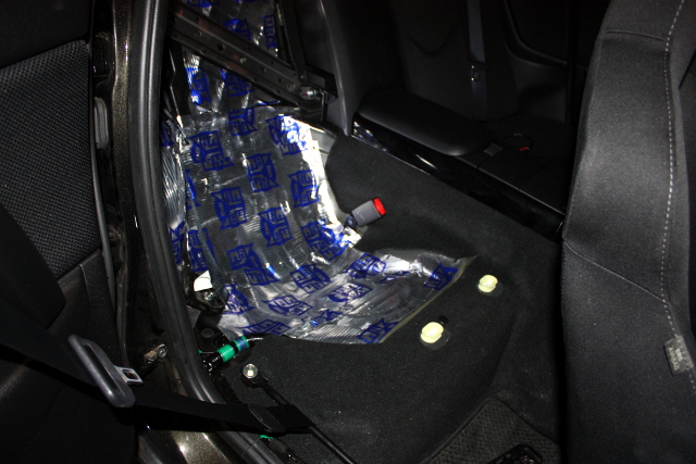
This job is not very difficult, more time is spent removing interior components like the rear
seats and the side rail trim.
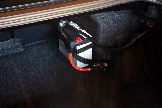
Once the trim piece are removed, you can easily pull the welding cable up towards
the front of the car from the trunk. What I did was take the wire up the passenger side
rail and then behind the dash, over to the driver side, and through the firewall grommet. Once
in the engine bay I ground off some paint from the car frame, and hooked up the ground wires.
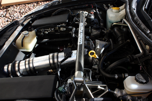
For the positive cable, I attached the OEM positive wire harness to a distribution block and
connecte the positive relocation wire to the block.
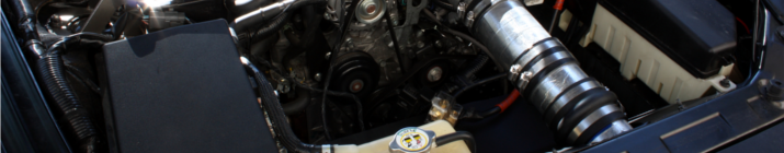
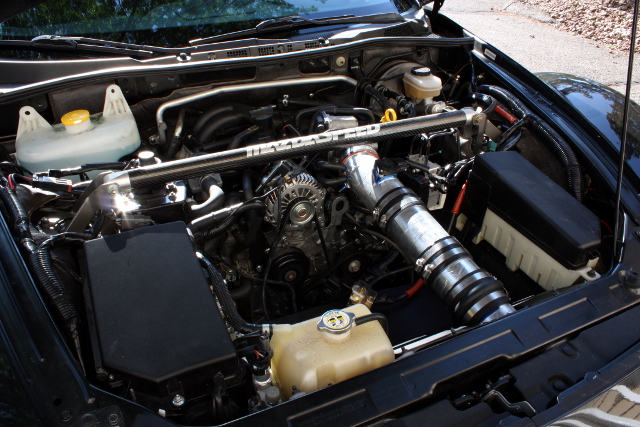
What I did afterwards was fabricate a little aluminum plate that bolts to the oem battery and
airbox locations. This helps to hide away some wires and protect the engine bay.
Lastly, for added safety, the circuit breaker was added close to the battery on the positive
cable. This will prevent the wire from transferring a dangerous short through the passenger
compartment should something happen.
Results
When I first completed the mod, the car was very slow to crank and turn over. This is a big
sign of a ground issue. After realizing that the block didn't have a good ground to the frame,
I added a short length of 4AWG wire to the block from the frame where I ran up the negative wire.
Once that was done, the car turns over a lot better now. I will have to give it a few more days
to make sure that the battery stays strong enough for daily use or if we may need to run a ground
directly to the starter.
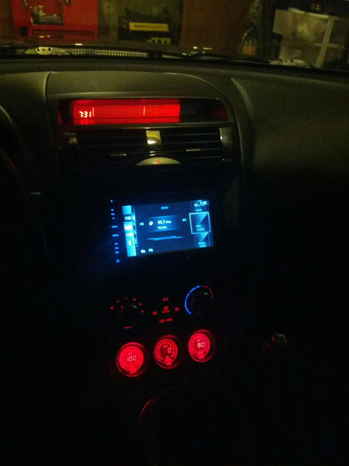
Soon after I purchased the RX8, I realized it was quickly going to be come my favorite hobby, and after reading up a lot about the car, I knew that it was a car that would need a lot of attention to keep running like brand new, and that was something I was looking forward to. In line with that thought, I wanted to know everything about the car, and to be able to monitor the critical items to make sure everything was in working order. The car has the typical water temperature gauge, but anyone who has owned a car knows that the gauge operates in three modes ... off, on, and overheat. Unlike its production rival the 350/70Z, the car didn't come with any oil pressure or temp gauges, or anything of that sort.
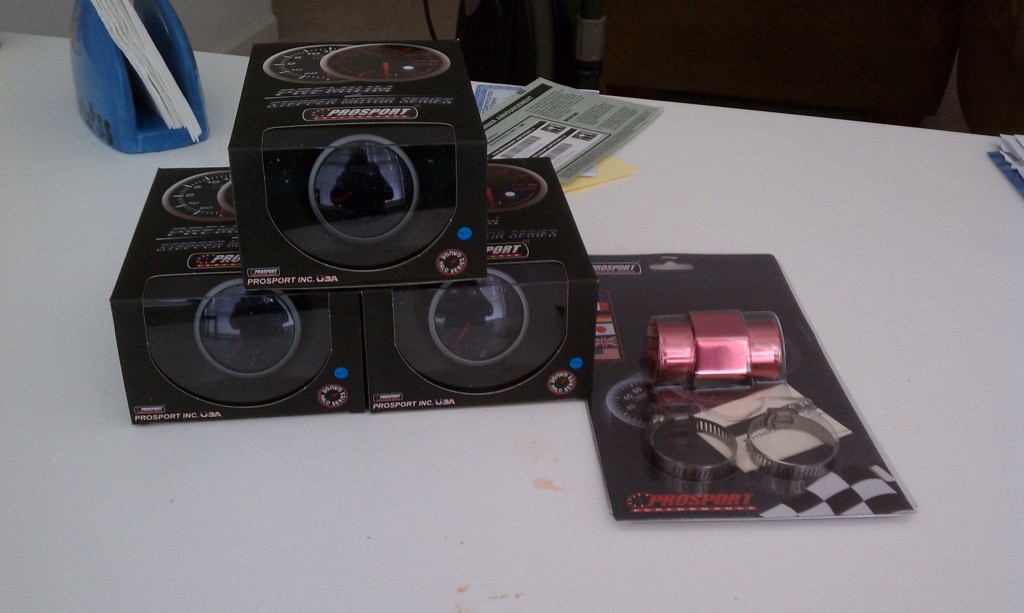
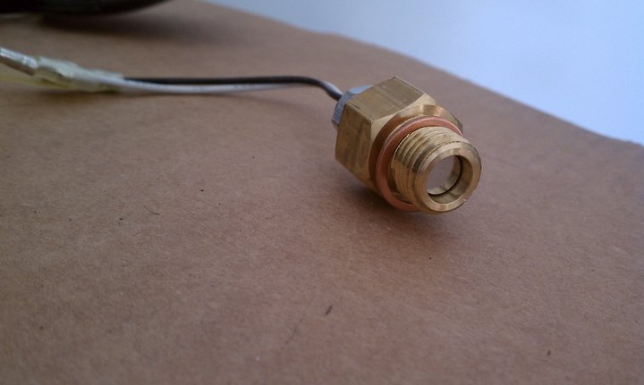
After some research, I came across the Prosport company which has an amazing reputation. It's gauges are made with quality parts, and are just as good as the more expensive brands. After contacting the company and getting a great deal, I had to jump on the offer. Pictured above is the water temp, oil temp, and oil pressure gauges, as well as the water temp sender adapter for the upper radiator hose.
Items Used
There are a significant number of parts that were used in this installation:
Unfortunately, they don't make a Lotek pod for the 2009-2011 RX8, so there will be a bit of fabrication that is needed, which is why I ended up ordering an extra speaker grill. Also, on top of the hardware listed above, you will also need a rotary cutting tool like a Dremel, some silicone, plastic clamps, and a LOT of patience. Lastly, take great care to protect your eyes and your mouth, you don't want to be breathing in the plastic, and you sure don't want a piece of your cutting tool flying in your eye.
Laying Out the Design
Before we start masking in cutting, we need to get familiar with what the product is intended to look like. The first think I did was to lay the Lotek pod on the center dash to get an idea of where I need to make my cuts.
If you look closely, you can see that the bottom of the Lotek pod (the part that faces close to you) lines up with the top of the information display. What this meant was that it was safe to cut off the lip that peers down as it wont help anything with this model RX8. Next, now that we have an idea of how the pod is going to sit, it would be nice to get a dry fitting of the gauges to make sure that no additional modifications will be necessary.
I personally favor a nice angle to the gauges, but that's something we can play with at the end. For now, it looks like the gauges fit nicely and we wont have to do anything to have that happen. So the next step is to start masking and cutting!
Masking
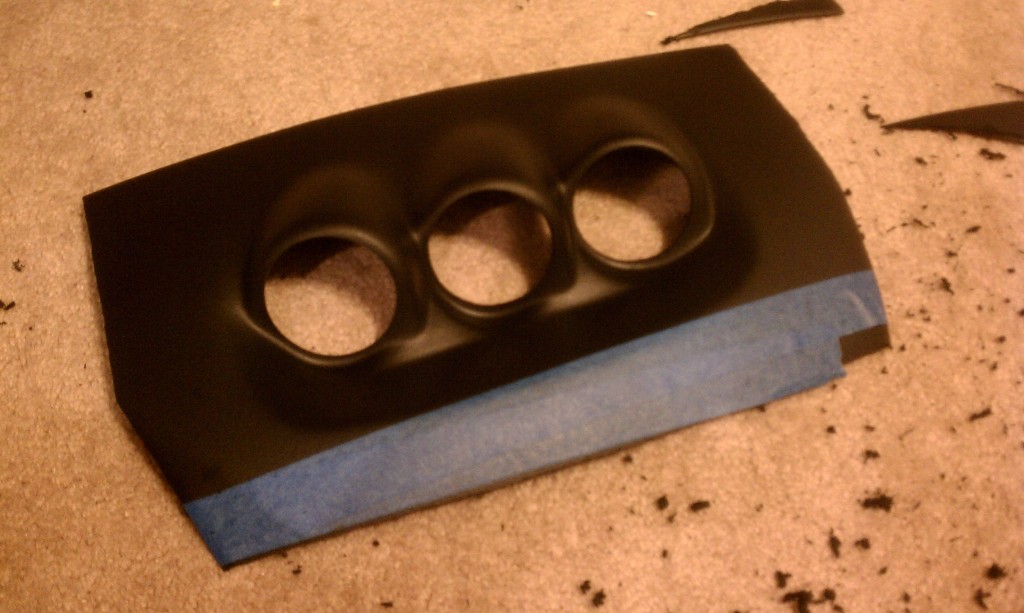
Make sure you have a good roll of painters tape, because if you are anything like me, one mask isn't good enough. I masked, cut, masked, cut, over and over until I was 100% sure I was not going to cut too far into the pod.
In the image above, you can see where I masked and the start of the cutting. If you have never worked with a Dremel before, this is the part you get to play around a little without ruining the pod. Start off with a low speed until you get the hang of the tool, then slowly move the speed up to a point where you are balancing speed and control. Be VERY careful not to tilt the Dremel while you are cutting or you are going to snap the cutting tool and have a shard fly somewhere.
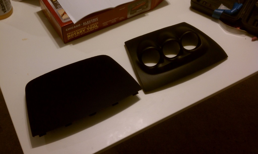
As you cut a little off, go back, sit the pod on the car, and measure. I did this numerous times just to get an idea of exactly what pieces are going to come off indefinitely. This is where the extra speaker grill will come in handy if you ordered one. I used it as a template for my cutting so that I could make sure to match the exact size of the dash.
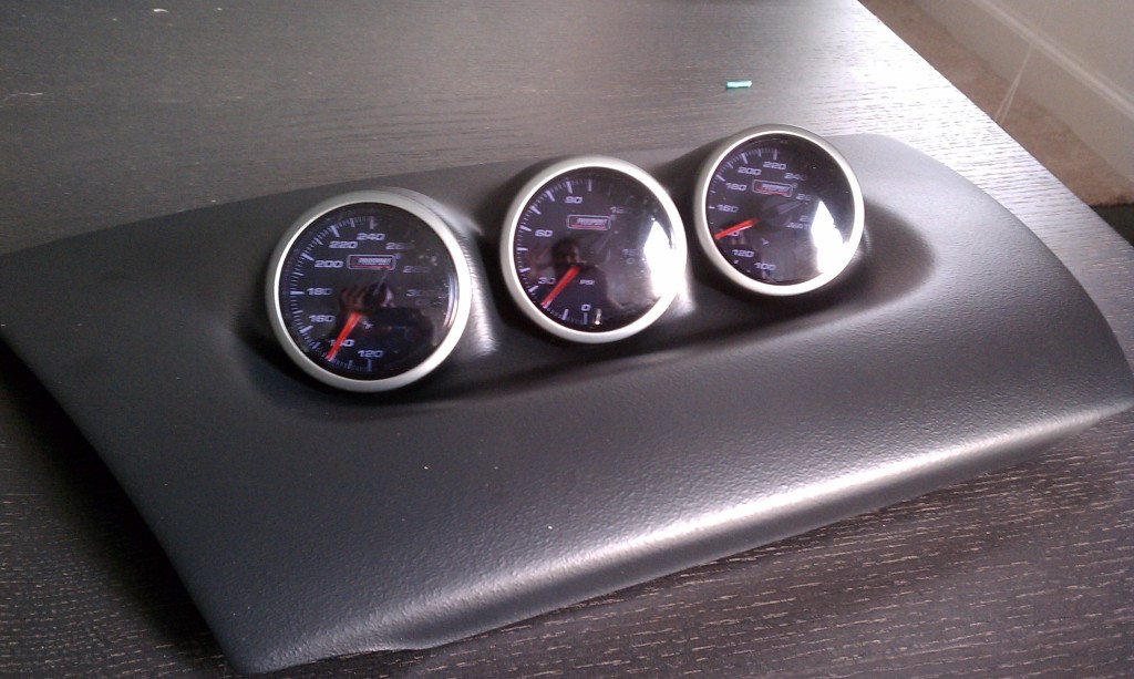
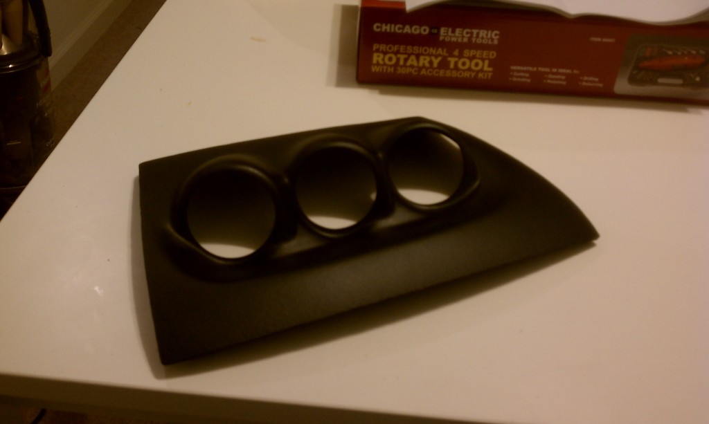
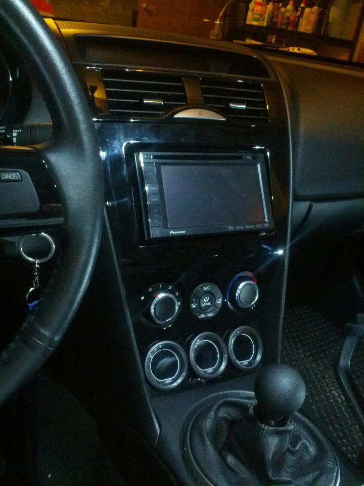
Finished Pod
As long as you took your time, and spent the majority of it measuring, you should be lucky enough to end up with a nicely fabbed product. The cut pod should now match the length of the speaker grill, and the front of the pod should line up exactly with the grill. You will notice that my pod is a bit longer at the top, which is fine since the cups that hold the gauge mold that far back.
Cutting The Speaker Grill
My initial intent was to take the pod the way it was, and some how pin it down to the dash with velcro or something stronger, however, it quickly became apparent that due to the shape and material of the plastic, it wouldn't be possible, or very safe. Unfortunately I didn't take pictures of this process, but what I did was slowly start cutting the grill from the middle outward. Again, checking the fitment by placing the pod on top of the grill from time to time, I kept cutting until all I was left with was the outer perimeter of the grill, with the posts that clip into the dashboard intact.
The next step from here was to line the entire bottom of the pod and grill with the silicone. Then, once fitted, I used 4 plastic clamps to secure the two together while they dried overnight. This made a very strong bond, and added some nice heft to the entire pod, and made it so that it seamlessly fit onto the dash.
Power Wiring
Wiring is relatively easy if you have an add-a-circuit, some patience, and an extra set of hands. Power wiring is very easy, because you can daisy chain all of the pods together. To successfully perform this task, you need long lengths of wire so that you can route power from the pod, down the stereo compartment, along the steering column, and then down to the fuse box. There are only three wires that you should be routing, the one for the constant power, one for the ignition power, and the ground. The dimmer wire will be going to another location so don't worry about that one for now.
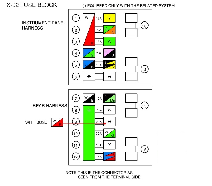
If you successfully routed the wires, the next thing you want to do is connect them to your add-a-circuit. For the constant power, you want to connect your A-A-C to the Room fuse which is fuse #12, and the ignition power can be installed to fuse #1. The ground wire can be installed anywhere that you have a bare piece of metal. A lot of people try and use the bolt behind the cabin fuse box, but for me the nut would not ease off, so instead I used the bolts that secured the clutch to the frame of the vehicle. The last wire that you need to connect is the dimmer wire, and unfortunately, there is nothing in the cabin fuse box that is only on when the dimmer is switched on, so instead, we can choose the easiest route and fish the wire from the pod, and over to the glove box. The next thing I did was tap into the red wire on the light of the glove compartment since this light is turned on when the dimmer is on.
Routing The Sender Wires
If you have had any experience with installing a big audio system in your car, or anything that requires power directly from the battery, you will have an idea on how to get the wires through the firewall. The sender wires are all similar lengths, and can be bundled together which makes it easier to route from the pod, across the steering column, and through the car's firewall.
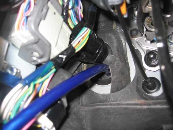
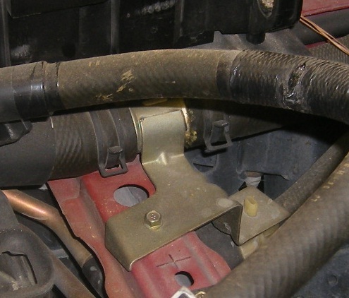
If you look above the pedals, you will notice a rubber grommet at the top left of the firewall which is wrapped around the main car harness. This part can be very dangerous if you do not take your time, so really get down in there, use a flashlight, and grab a small sharp knife. The safest location to punch through the firewall grommet is the bottom right, farthest away from the wiring harness. The photo below which is from a stereo installation over at the rx8club.com forums can give you an idea of what you are looking to do. Take not how the large blue wire is going through the bottom right of the grommet.
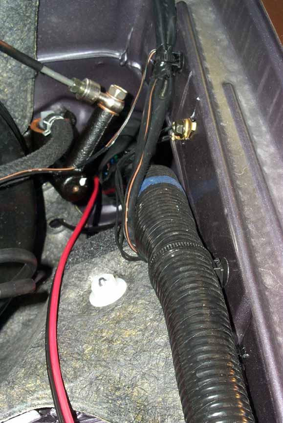
Once you have punched a large enough hole, gently fish your wires through to the other side. Don't worry about pushing the entire wire loom out as you can easily just pull it all out from the engine bay. So next, pop the hood and look at the top right of the engine bay below the brake booster. If you are lucky, you will see the wires you fished through right away.
Slowly pull the wires so that you have very little slack in the interior. The only sender wire that will take the longest path will be the one that connects to the water adapter.
Wiring The Senders
The three senders are very easy to install and here we will discuss how to install them in the order of easiest to hardest (which isn't really hard at all, just time consuming).
Oil Pressure Sender
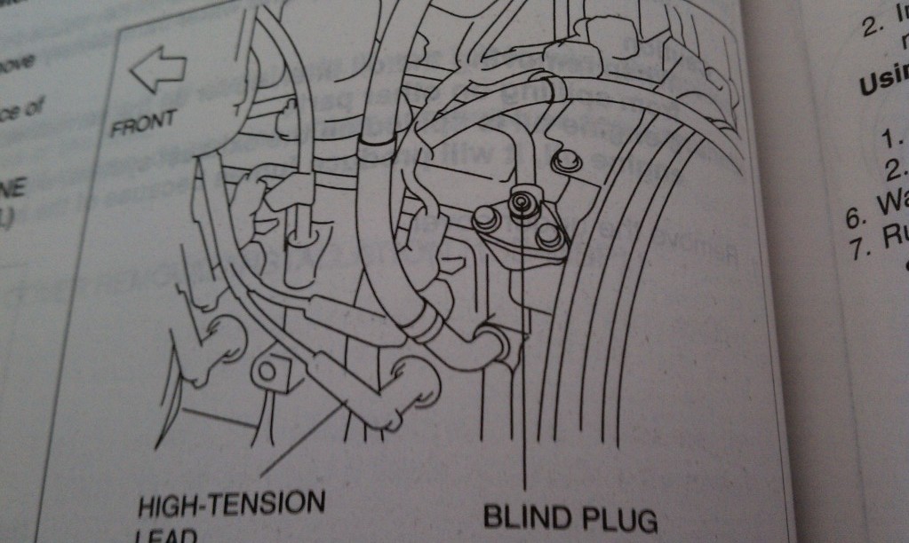
The Series 2 RX8 engine provides us with an easy way to read the oil pressure from a small port on it's side. If you look just behind the rear trailing plug, you will notice a small hex screw that is covering a hole. Refer to the image below from the Mazda service manual
After removing the plug labeled "BLIND PLUG", you can then screw in the oil pressure sender and plug in it's wiring.
Oil Temperature Sender
Unfortunately there is no port to read the temperature of the oil, and not enough oil flows through the BLIND PLUG port to get a significant oil temperature reading, so the next best thing is to install the sender directly to the oil pan. This can be done very easily, by replacing your oil pan plug with a converter plug that converts the 1/8" size of the sender to the metric size of the drain plug.
Of course this means that you are going to have to drain your oil so you can install that, but with this car, that's not necessarily a bad thing. Once you install the plug, route your sender wires down and make sure you have a nice tight connection to the sender.
Water Temperature Sender
This part takes the longest, as it will require you to first drain all of the coolant from the car from the plug underneath the radiator, and remove the battery as well as the battery cage from the engine bay. Once you have successfully done that, you will notice the coupler that is used to connect the two pieces of the upper radiator hose together. This piece is screwed into the frame of the car, so it can easily be removed.
The hose clamped onto the coupler on both sides with these very strong clamps, make sure to use a pair of pliers or a specialty tool to remove the clamps without damaging the hoses. Once removed, install the water adapter with the hole facing out to the side. Next, wrap the sender's threads in some plumbers tape, and install the sender, making sure to get a nice tight install so that there are no leaks. Use the provided clamps as a replacement for the OEM ones, and ensure a tight fitment. Lastly, connect the sender wires, and reconnect the battery, you do not want to reinstall the battery supports just yet, because we want to check to make sure the sender works and the hoses aren't leaking.
Installation Complete
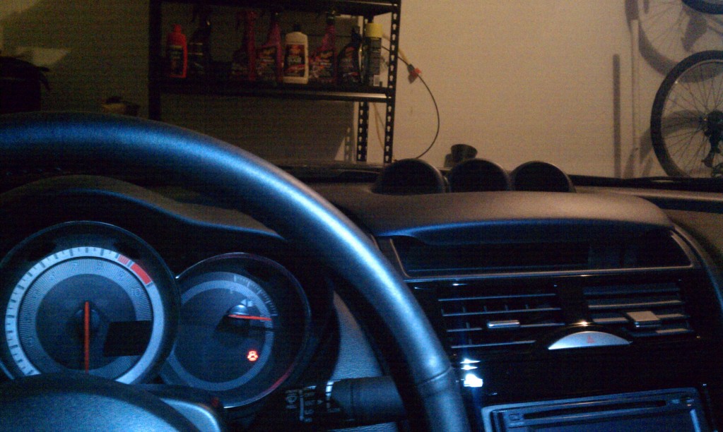
Before cleaning up and putting everything away, lets make sure that the install went according to plan. You will first need to refill your engine oil, as well as the engine coolant. Next, turn the car onto ACC mode and lets check to see if the gauges come on
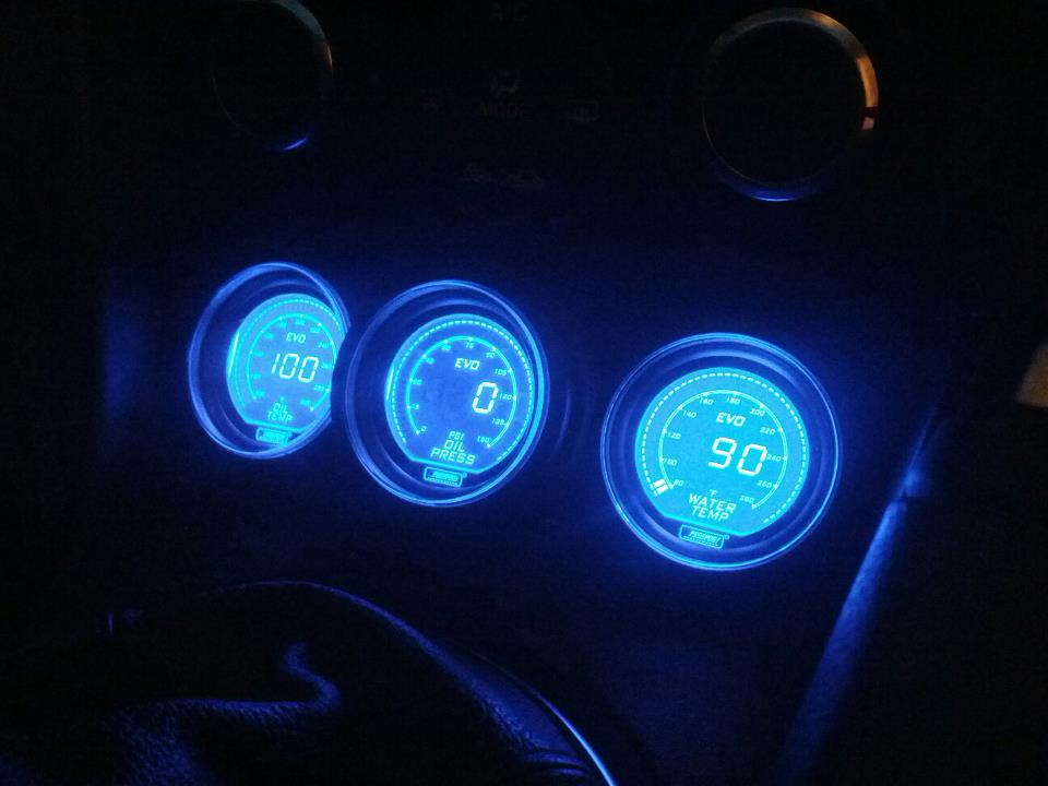
If all went well, lets fire the car up and check the reading of the gauges (dont mind the middle gauge in the video below, this was before I had the adapter for the oil temperature)
Take note, that you are not going to see the water temperature immediately as the upper radiator hose only gets a flow of water when the thermometer opens up. If this is the first time you are turning the car on after the coolant refill this is the best time to test the gauge. Turn the heater on full blast so that the coolant flows through the entire HVAC system. Eventually the thermometer will open and you should see the water temp start to read the temp.
Going the Extra Mile
The Halo series of the gauges come with a small remote that is used to set the peak, warning, sound, dimming, and the backlighting of the gauges. One could easily cut a small notch into each of the gauge pod holes to fit the wires through, and tape (provided) the remotes to the side of each gauge, however, I wanted something more stealth.
This requires a bit of work as you need to extend the wires to the remote harness, and fish them through the dash down to the ashtray.
Updates
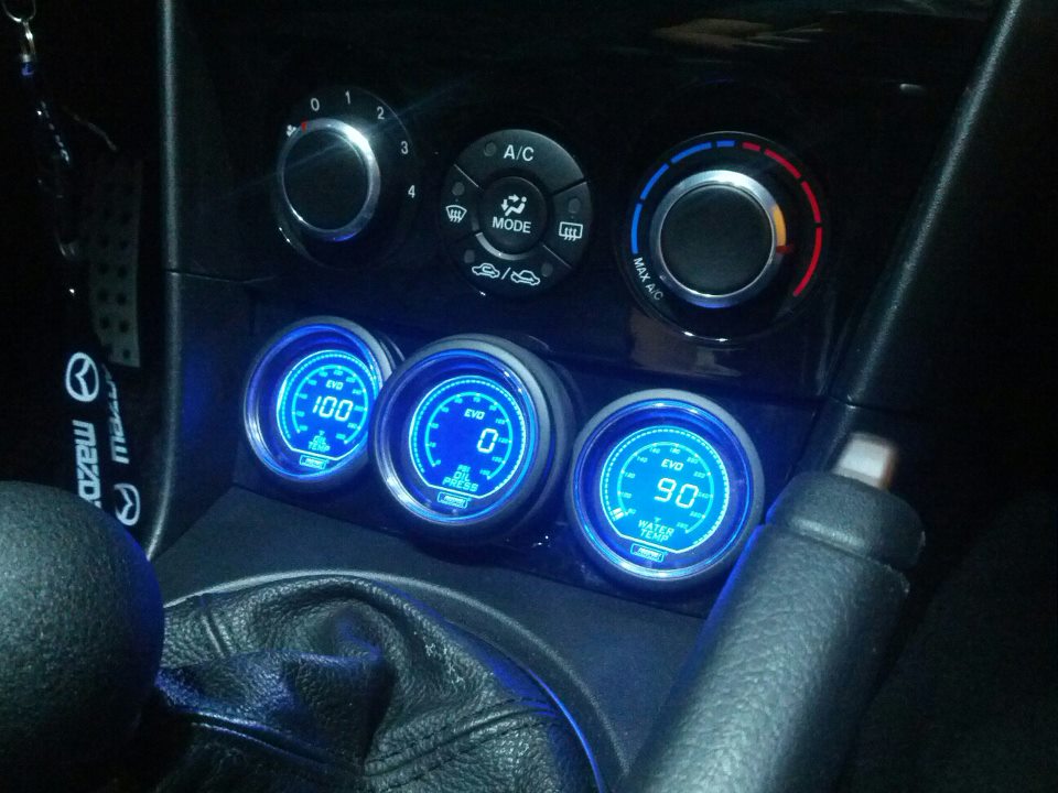
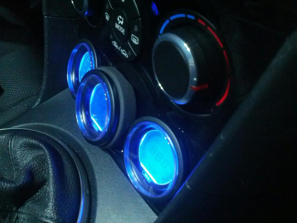
After a few years of using the custom gauge pod, I decided it was time for an update. One of the cons of the gauge pod was that it would have the gauges sit at a strange angle. Although the gauges were readable, they were prone to glare. After getting some ideas from looking at the Racing Beat pod, I decided to make some changes.
Along with the changes, I upgraded my gauges to the new line of Prosport EVO gauges. These all digital gauges are quite nice, with easy to read numbers, and a sweeping digital indicator around the edge. This gauge pod was custom made by using a hole saw and some metal bracing on the back side to prevent flexing.
There are few available options provided by Mazda to help deter theft of the vehicle and its contents. Along
with a 'chipped' ignition key, there are also options for a Mazda OEM shock sensor to be installed. This device
can be installed either by the dealer, or at home with a few tools. With this installed in the vehicle, the user
can dial in the sensitivity in which the alarm will be triggered should the vehicle experience a shock or rocking.
There are currently instructions bundled with the OEM shock sensor, however these instructions are only geared
towards the installation on a series 1 (2003-2008) RX8. The wiring has changed a little bit between the two
generations, and one wire in particular would prevent the shock sensor from operating properly if the bundled
instructions are used. Please be aware that this will NOT work for those with the advanced key.
Required Tools
There are a few tools required to be able to do this job successfully.
Mazda OEM Shock Sensor
Wire Cutters
Pliers
Getting Started
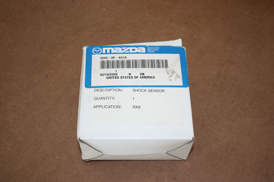
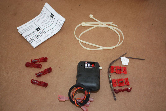
To get started, we will open the contents of the package and investigate the contents. The box should have the following:
Instructions
Small Wire taps (5)
Large Wire Taps (2)
Wire w/ Diode
Shock Sensor w/ Harness
Zip Ties (2)
Access Passenger Kick Panel
The first step is to get clear the passenger side of your car to work in. Removing the floor mats is recommended so you
can easily access the kick panel. The next thing you want to do, is to pull up on the front of side panel that runs
along the door frame. The reason you want to do this is because part of the kick panel runs underneath this.
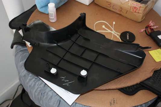
Next, remove the kick panel by pulling out the rear first. Do not try to remove from the front (the part closest to the
seat), as there are tabs that may break. Work your way from the rear of the panel, to the front of the panel along the
bottom. There are two plastic snap on clips, and two tabs. The image below shows what the kick panel looks like from
the inside.
Wiring
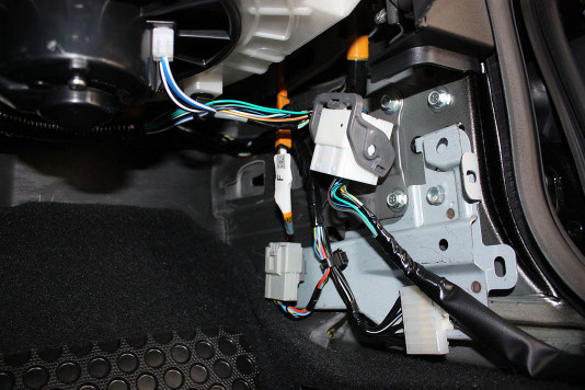
Next, you will notice three connecting harnesses that sit behind the kick panel. The one at the bottom left is the
one we will primarily be working with, and the one on the bottom right is where our ground will go. The larger
harness near the top will not be used in this installation.
To make working with the primary harness easier, you can easily unclip it from the metal frame by sticking a finger
behind, and pushing outwards. These harnesses are clipped in with very weak clips, so it shouldn't take much effort
to remove.
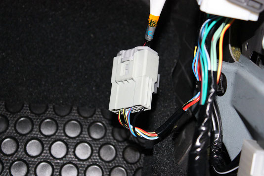
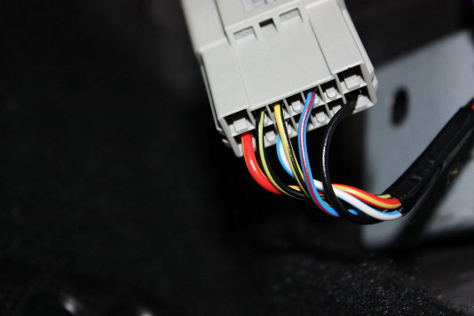
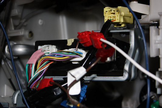
There are two wires on this harness that we need to focus on, the BLACK with YELLOW STRIPE and the BLUE with RED
STRIPE. For reference, these are found on the top row, pins 2 and 5 from the left.
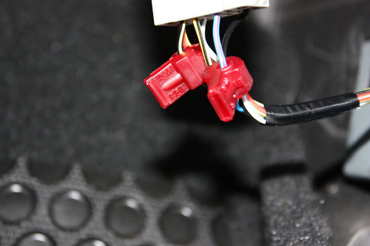
Take the supplied wire taps, and connect one to each of the wires mentioned in the last post. I found it easy to
support the clip with one hand, while crimping it shut with a set of pliers with the other hand. Unfortunately
the wires are a tad bit too thick, and the taps are too dull to do this by hand
Wiring Cntd.
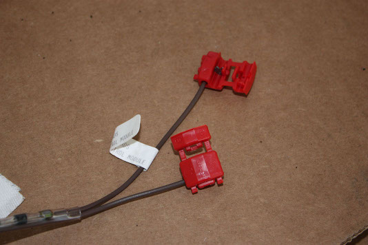
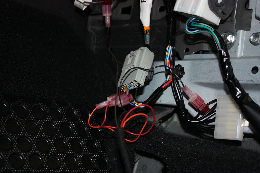
The next thing we need to do is to prepare the trunk trigger diode. The kit comes with a wire that has a diode
pre-installed. All we need to do is to prepare the wire by installing the large butterfly taps to each end.
What you want to do is to take the butterfly tap, and locate the end WITHOUT the stopper, this is the end that
will go to the supplied diode wire. The other side we want to make sure that the open end is facing away from
the diode. In the picture above, take note of the orientation of the open wing of the tap, notice where the
open (longer, unblocked) end is facing, this is very important.
The final wire that we need to tap into is a ground. The harness connector that is at the bottom right of the
three that was displayed in the second posting in this thread is full of grounding wires. Feel free to use any
of the SOLID BLACK ONLY wires. There is one wire in this bundle that has a stripe on it, make sure you do NOT
use that one.
The next part really took me a while since the instructions weren't very informative, and any DIY i found online
pointed to an older gen RX8 which has a different harness setup behind the kick panel. What we need to locate is
the brown/white trunk light trigger wire. This is NOT in any of the three harnesses displayed earlier in this
thread. Instead, it is located at the keyless entry module.
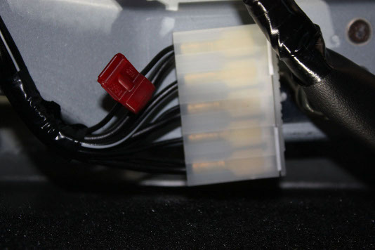
You will need to remove the glove box for this, and behind there, you will see the keyless entry module with
three harnesses connected to it. The harness in the middle is the one we want to find the wire in. Along the top
row, at the far right, you should find the brown/white wire. Snip that wire. IMPORTANT Next, take the
brown wire assembly that we made earlier, and make sure that the flag side is connected to the brown wire coming
from the keyless entry module, while the non flag side is going back down away from the keyless entry module.
This is very important, if you mess this part up, you will damage the shock sensor
Note, you will realize that by placing this wire here, the original harness may not reach, you can improvise here
by taking some standard 18gauge wire and tapping the label side and running it down the passenger kick panel.
Wiring Harness
Now that all of our wires have been tapped into, we can connect the shock sensor harness up. The wiring is as follows:
[Shock sensor Harness] ----- > [Vehicle Wire]
Red Wire ----- > BLUE/RED Wire
Orange Wire ----- > BLACK/YELLOW Wire
Brown Wire ----- > Diode Assembly Brown Wire (label side)
Black Wire ----- > Black Wire
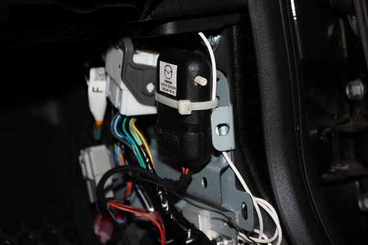
Now that the wires are connected, we are ready to test the sensor. First thing we want to do, is to turn the adjustment
knob all the way counter clock wise. This is the Least Sensitive setting. Next, using the zip ties provided, tie the
shock sensor to the bundle of wires that runs between the two connectors. Make sure that you orient the sensor in
such a direction that you can easily access the adjustment knob. Do not worry about shock sensor orientation, it will
not impact it's performance.
Next, close all of the doors, and lock the car with the keyless entry remote. Press lock twice to arm the system. Now,
the car should not sound on any light impact, this is very important as you dont want you alarm going off whenever a
car drives by. The security system should only trigger on heavy impact to the vehicle. The instructions recommend
testing the shock sensor by bouncing a tennis ball off of the windshield. If the alarm triggers, it should be turned
down a notch and retested until it does not trigger when the tennis ball ricochets off. An alternative test is to just
open palm slap the windshield.
IMPORTANT: If the alarm is not triggering no matter what sensitivity setting you choose, then you may have installed
the diode assembly backwards. If this occurs, you need to replace the shock sensor after correcting the connection.
Once you have confirmed that your system works, you can neatly bundle up the wiring, and reinstall the kick panel.
 Mobile Menu