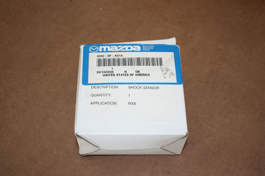
2009 - 2011 RX8 Shock Sensor

-
Installing Mazda Shock Sensor
There are few available options provided by Mazda to help deter theft of the vehicle and its contents. Along
with a 'chipped' ignition key, there are also options for a Mazda OEM shock sensor to be installed. This device
can be installed either by the dealer, or at home with a few tools. With this installed in the vehicle, the user
can dial in the sensitivity in which the alarm will be triggered should the vehicle experience a shock or rocking.
There are currently instructions bundled with the OEM shock sensor, however these instructions are only geared
towards the installation on a series 1 (2003-2008) RX8. The wiring has changed a little bit between the two
generations, and one wire in particular would prevent the shock sensor from operating properly if the bundled
instructions are used. Please be aware that this will NOT work for those with the advanced key.
-
Required Tools
There are a few tools required to be able to do this job successfully.
- Mazda OEM Shock Sensor
- Wire Cutters
- Pliers
-
Getting Started
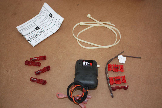
To get started, we will open the contents of the package and investigate the contents. The box should have the following:
- Instructions
- Small Wire taps (5)
- Large Wire Taps (2)
- Wire w/ Diode
- Shock Sensor w/ Harness
- Zip Ties (2)
-
Access Passenger Kick Panel
The first step is to get clear the passenger side of your car to work in. Removing the floor mats is recommended so you
can easily access the kick panel. The next thing you want to do, is to pull up on the front of side panel that runs
along the door frame. The reason you want to do this is because part of the kick panel runs underneath this.
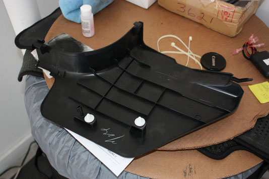
Next, remove the kick panel by pulling out the rear first. Do not try to remove from the front (the part closest to the
seat), as there are tabs that may break. Work your way from the rear of the panel, to the front of the panel along the
bottom. There are two plastic snap on clips, and two tabs. The image below shows what the kick panel looks like from
the inside.
-
Wiring
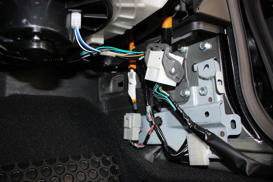
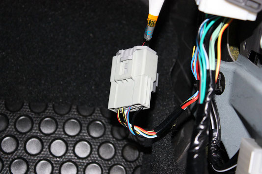
Next, you will notice three connecting harnesses that sit behind the kick panel. The one at the bottom left is the
one we will primarily be working with, and the one on the bottom right is where our ground will go. The larger
harness near the top will not be used in this installation.
To make working with the primary harness easier, you can easily unclip it from the metal frame by sticking a finger
behind, and pushing outwards. These harnesses are clipped in with very weak clips, so it shouldn't take much effort
to remove.
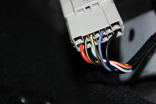
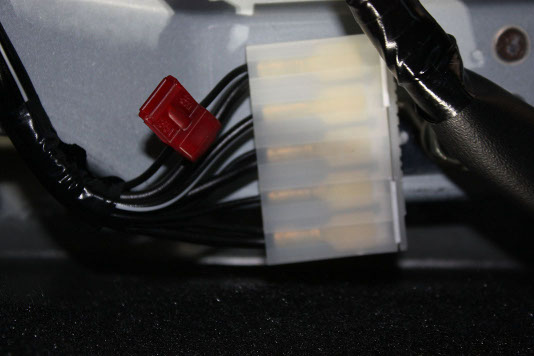
There are two wires on this harness that we need to focus on, the BLACK with YELLOW STRIPE and the BLUE with RED
STRIPE. For reference, these are found on the top row, pins 2 and 5 from the left.
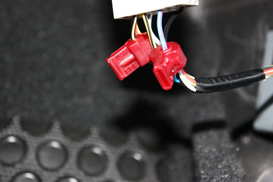
Take the supplied wire taps, and connect one to each of the wires mentioned in the last post. I found it easy to
support the clip with one hand, while crimping it shut with a set of pliers with the other hand. Unfortunately
the wires are a tad bit too thick, and the taps are too dull to do this by hand
-
Wiring Cntd.
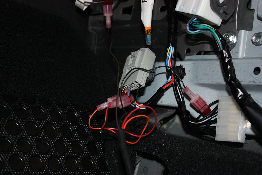
The next thing we need to do is to prepare the trunk trigger diode. The kit comes with a wire that has a diode
pre-installed. All we need to do is to prepare the wire by installing the large butterfly taps to each end.
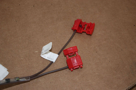
What you want to do is to take the butterfly tap, and locate the end WITHOUT the stopper, this is the end that
will go to the supplied diode wire. The other side we want to make sure that the open end is facing away from
the diode. In the picture above, take note of the orientation of the open wing of the tap, notice where the
open (longer, unblocked) end is facing, this is very important.
The final wire that we need to tap into is a ground. The harness connector that is at the bottom right of the
three that was displayed in the second posting in this thread is full of grounding wires. Feel free to use any
of the SOLID BLACK ONLY wires. There is one wire in this bundle that has a stripe on it, make sure you do NOT
use that one.
The next part really took me a while since the instructions weren't very informative, and any DIY i found online
pointed to an older gen RX8 which has a different harness setup behind the kick panel. What we need to locate is
the brown/white trunk light trigger wire. This is NOT in any of the three harnesses displayed earlier in this
thread. Instead, it is located at the keyless entry module.
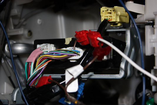
You will need to remove the glove box for this, and behind there, you will see the keyless entry module with
three harnesses connected to it. The harness in the middle is the one we want to find the wire in. Along the top
row, at the far right, you should find the brown/white wire. Snip that wire. IMPORTANT Next, take the
brown wire assembly that we made earlier, and make sure that the flag side is connected to the brown wire coming
from the keyless entry module, while the non flag side is going back down away from the keyless entry module.
This is very important, if you mess this part up, you will damage the shock sensor
Note, you will realize that by placing this wire here, the original harness may not reach, you can improvise here
by taking some standard 18gauge wire and tapping the label side and running it down the passenger kick panel.
-
Wiring Harness
Now that all of our wires have been tapped into, we can connect the shock sensor harness up. The wiring is as follows:
- [Shock sensor Harness] ----- > [Vehicle Wire]
- Red Wire ----- > BLUE/RED Wire
- Orange Wire ----- > BLACK/YELLOW Wire
- Brown Wire ----- > Diode Assembly Brown Wire (label side)
- Black Wire ----- > Black Wire
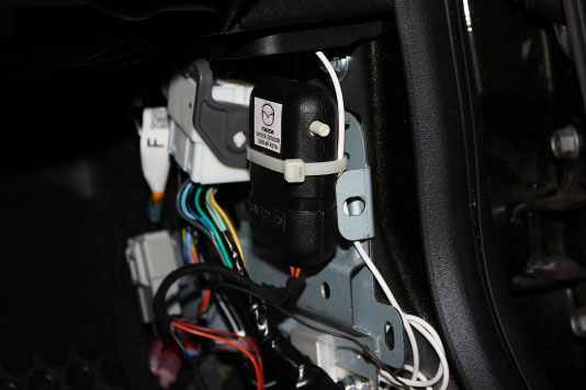
Now that the wires are connected, we are ready to test the sensor. First thing we want to do, is to turn the adjustment
knob all the way counter clock wise. This is the Least Sensitive setting. Next, using the zip ties provided, tie the
shock sensor to the bundle of wires that runs between the two connectors. Make sure that you orient the sensor in
such a direction that you can easily access the adjustment knob. Do not worry about shock sensor orientation, it will
not impact it's performance.
Next, close all of the doors, and lock the car with the keyless entry remote. Press lock twice to arm the system. Now,
the car should not sound on any light impact, this is very important as you dont want you alarm going off whenever a
car drives by. The security system should only trigger on heavy impact to the vehicle. The instructions recommend
testing the shock sensor by bouncing a tennis ball off of the windshield. If the alarm triggers, it should be turned
down a notch and retested until it does not trigger when the tennis ball ricochets off. An alternative test is to just
open palm slap the windshield.
IMPORTANT: If the alarm is not triggering no matter what sensitivity setting you choose, then you may have installed
the diode assembly backwards. If this occurs, you need to replace the shock sensor after correcting the connection.
Once you have confirmed that your system works, you can neatly bundle up the wiring, and reinstall the kick panel.
 Mobile Menu